
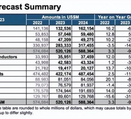
Global Semiconductor Sales Decrease 8.2% in 2023; Market Rebounds Late in Year Worldwide industry sales totaled $526.8 billion in 2023; market grew during second half of year and sales are projected to increase by 13.1% in 2024
VIEW MORE+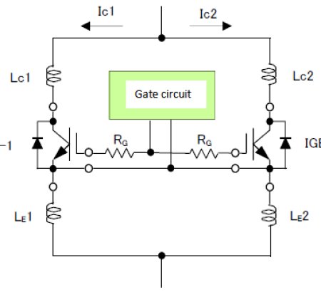
Due to the relationship between the gate-emitter connection inductance LG, RG, and Cies, if oscillation occurs in the gate drive loop, component damage may occur due to malfunction and unsaturated operation. The minimum value of RG without oscillation increases in proportion to √LG. Therefore, the inductance should be reduced as much as possible while keeping RG above the recommended value.
VIEW MORE+
BEIJING -- China has moved to set its own standards for semiconductors used in electric vehicles and self-driving cars as it seeks to replace imports of these vital components with domestic production.
VIEW MORE+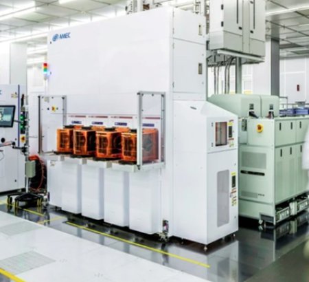
Shanghai-based AMEC expects its 2023 revenue to reach US$879 million, up 32.1 per cent from the previous year, on the back of strong domestic orders The company said sales of its core etching tools will account for 75 per cent of its total revenue last year
VIEW MORE+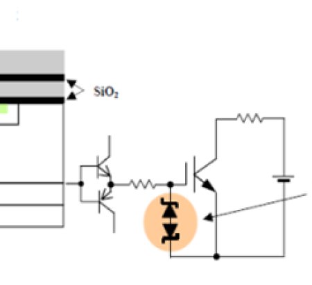
Rated gate drive voltage: When a voltage exceeding this range is applied to the gate drive voltage within the ±20V range, the oxide film (SiO2) between the gate and the emitter may suffer insulation damage or cause a decrease in reliability.
VIEW MORE+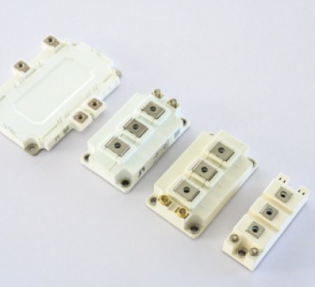
With the rise of emerging applications such as wind power generation, smart grid construction, electric vehicles, and high-voltage inverters, high-power IGBT modules are increasingly used. Correspondingly, the importance of IGBT reliability in high-power power supply design is increasing day by day. . System reliability has become one of the most important design indicators. The reliability of high-power switching devices is a top priority.
VIEW MORE+QINGDAO JIAEN SEMICONDUCTOR CO., LTD
Address: Unit 103-104, Building 41, No. 780 Baoyuan Rd, High-tech Zone, Qingdao, China.
Tel:+86 13792436358
Fax:+86-532-67769506
E-mail: vickywang@jiaensemi.com

FOLLOW US
Copyright© Qingdao Jiaen Semiconductor Co., Ltd.(Head Office),All Rights Reserved. Powered by:Hicheng SITEMAP