
PRECAUTIONS FOR PARALLEL CONNECTION OF IGBT COMPONENTS
Current balance when connected in parallel:
Due to the relationship between the gate-emitter connection inductance LG, RG, and Cies, if oscillation occurs in the gate drive loop, component damage may occur due to malfunction and unsaturated operation. The minimum value of RG without oscillation increases in proportion to √LG. Therefore, the inductance should be reduced as much as possible while keeping RG above the recommended value.
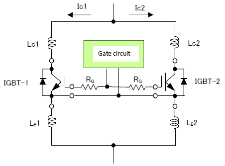
● The difference in distributed inductance is related to the imbalance of transition current during turn-on and turn-off. Please try to keep the collector and emitter connection lines between IGBTs the same and as short as possible.
● Please add a gate resistor to each IGBT element, make the inductance of each gate connection the same and use the gate connection wire as short as possible. Do not connect the gate wiring to the emitter to the main terminal, but to the dedicated (auxiliary) terminal.
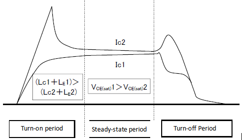
● The saturation voltage VCE(sat) of IGBT is affected by temperature. Please minimize the difference in temperature rise between modules.
VCE (sat) grade classification for parallel operation:
When working in parallel, in order to solve the current sharing problem of IGBT components, the actual operating current of each IGBT component can only be about 80% of its rated value. For example, when four 300A modules are connected in parallel, the total current is expected to be about 300×0.8×4=960A.
