
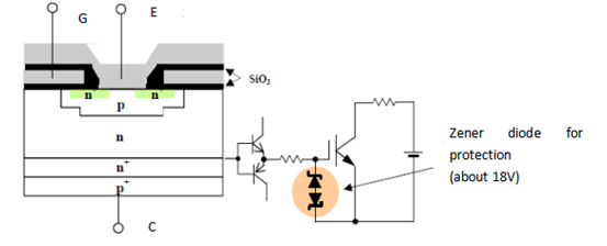
GATE DRIVER OF IGBT MODULE
Rated gate drive voltage: When a voltage exceeding this range is applied to the gate drive voltage within the ±20V range, the oxide film (SiO2) between the gate and the emitter may suffer insulation damage or cause a decrease in reliability.
Turn-on-gate drive voltage:
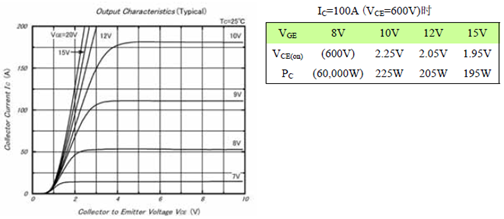
The standard turn-on gate drive voltage is +15V. Low gate drive voltages such as 12V and 10V will cause increased collector losses. At 6V, the IGBT is basically not turned on. At this time, the power supply voltage is applied to the collector-emitter. When such low gate voltages are applied, there is a risk of component damage due to excessive losses.
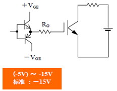
Gate reverse bias voltage when turned off (-VGE):
In order to avoid malfunction due to noise interference, please apply a reverse bias voltage of (-5V)-(-15V) to the IGBT gate when turning off.
The relationship between turn-on gate voltage, gate reverse bias voltage at turn-off and switching speed-noise interference:
If the turn-on gate voltage + VGE is increased, the turn-on speed will increase and the turn-on loss will decrease. On the contrary, the noise interference will increase when it is turned on. Similarly, if the turn-off gate voltage -VGE is increased, the turn-off speed will increase and the turn-off loss will decrease. On the contrary, the surge voltage and noise interference during shutdown will increase. +VGE, -VGE and the next RG are the main factors affecting the switching speed.
Gate impedance RG and switching characteristics:
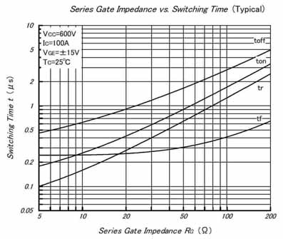
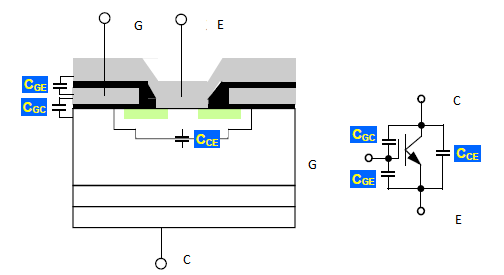
Gate capacitance:
Input capacitance: Cies = Cge + Cgc
Reverse Transfer Capacitance: Cres = Cgc
Output capacitance: Coes = Cce + Cgc
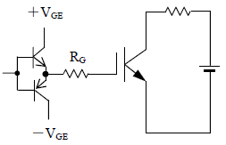
Emitter gate reverse bias voltage and gate-emitter impedance RGE:
Displacement current flows due to high dv/dt, and the gate potential rises.
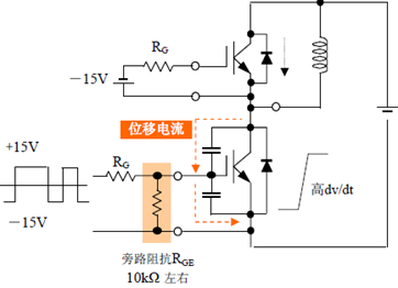
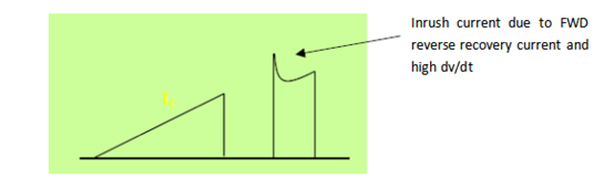
Gate reverse bias voltage and bypass resistor are effective in reducing inrush current (IGBT loss)
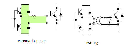
Gate Wiring: To avoid harmful oscillations, please note the following.
● Try to keep the gate wiring as far away from the main circuit wiring as possible and avoid making them parallel.
● When crossing, please cross at right angles.
● Do not bundle multiple gate wires together.
● Adding common mode choke coils and ferrite magnetic rings can also achieve certain effects.
Gate charge and drive current-power:
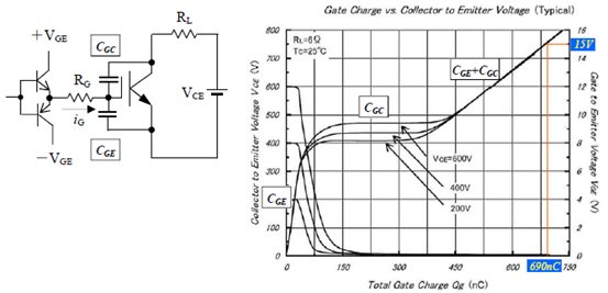
Calculation example of gate drive loss PG and maximum gate drive current iGP
(+VGE=15V, -VGE=-15V, f=10kHz) PG={(+VGE)-(-VGE)}×Qg×f=30×690×10-9×104=0.207 (W)
Assume it is turned on at 500ns;
iGP = Qg / ton=690×10-9 / 500×10-9=1.4 (A)
