The Asia-Pacific region commands the largest market share in power semiconductors, with an estimated CAGR of 3.6%. China, Japan, Taiwan, and South Korea collectively contribute around 65% of the global discrete semiconductor market, while countries like Vietnam, Thailand, Malaysia, and Singapore also play significant roles. North America follows closely, expected to reach USD 8.5 billion by 2030 with a CAGR of 2.6%. The region boasts early adoption of new semiconductor technologies, particularly in automotive, IT, telecommunications, military, aerospace, and consumer electronics.
VIEW MORE+
Singapore’s RF GaN chip vendor Gallium Semiconductor is closing its doors, including those of its R&D center in Nijmegen, The Netherlands. The decision to shut the company and let go of all the employees has been made by GaasLabs LLC, the investment company that wholly-owns Gallium Semiconductor and has funded it since it was founded in 2020. The decision was made following the death in November 2023 of John Ocampo, the founder of GaasLabs.
VIEW MORE+
Recently, the Private Economic Development Bureau announced the list of Qingdao's 2023 small and micro enterprise innovation and transformation projects. Our company was successfully selected. At the same time, we would like to thank everyone for their high recognition and affirmation of Jiaen Semiconductor. Jiaen Semiconductor, as a new generation of power semiconductor design company, masters the core technology of innovative power semiconductors and has independent intellectual property rights and independent brands. The company's independently developed products cover 600V~1200V IGBT chips, 500V~1500V MOS chips, and 400V~1200V FRD chips. It has applied for a total of 33 invention patents and 36 utility model patents, and has currently authorized 8 inventions and 33 new models. Through the evaluation of a third-party authoritative organization, the company's core IGBT chip technology has reached the international advanced level, and the products are ahead of domestic companies in reducing on-resistance, inverting current, especially in terms of reliability.
VIEW MORE+
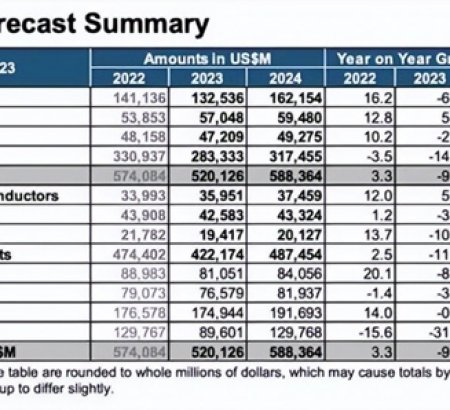
Global Semiconductor Sales Decrease 8.2% in 2023; Market Rebounds Late in Year Worldwide industry sales totaled $526.8 billion in 2023; market grew during second half of year and sales are projected to increase by 13.1% in 2024
VIEW MORE+
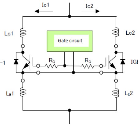
Due to the relationship between the gate-emitter connection inductance LG, RG, and Cies, if oscillation occurs in the gate drive loop, component damage may occur due to malfunction and unsaturated operation. The minimum value of RG without oscillation increases in proportion to √LG. Therefore, the inductance should be reduced as much as possible while keeping RG above the recommended value.
VIEW MORE+
BEIJING -- China has moved to set its own standards for semiconductors used in electric vehicles and self-driving cars as it seeks to replace imports of these vital components with domestic production.
VIEW MORE+