
Application of third-generation semiconductor power devices in the automotive industry
VIEW MORE+
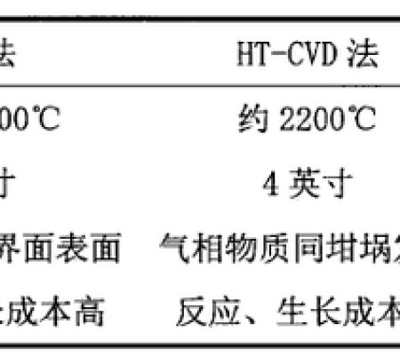
Silicon carbide has excellent electrical properties such as high voltage resistance, high temperature resistance, high frequency, and radiation resistance. It breaks through the physical limitations of silicon-based semiconductor materials and becomes the core material of the third-generation semiconductor. The performance advantages of silicon carbide materials lead to new changes in power devices.
VIEW MORE+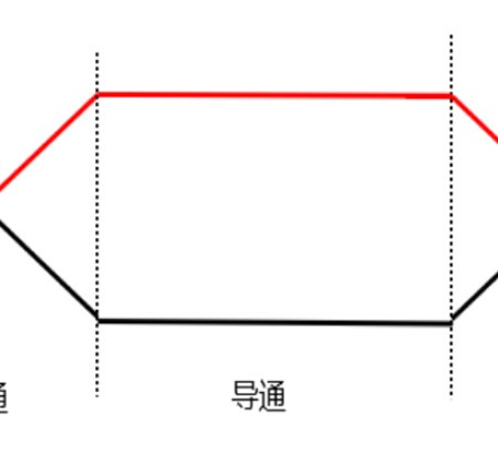
In the vast field of power electronics, the insulated gate bipolar transistor (IGBT) is a core device, and its performance is directly related to the operating efficiency and stability of the entire system. The power consumption problem has always been a key link that cannot be ignored in the application of IGBT. Today, let us explore the mystery behind the power consumption of IGBT.
VIEW MORE+
The reverse recovery phenomenon of the IGBT module refers to some specific physical phenomena and changes in electrical characteristics that occur when the integrated freewheeling diode (FWD) inside the IGBT changes from the forward conduction state to the reverse cutoff state when the IGBT is turned off.
VIEW MORE+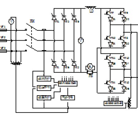
In the field of modern industrial electrical power, medium frequency power supplies are widely used, and IGBT (insulated gate bipolar transistor) plays a vital role as the core device of medium frequency power supplies. This article will deeply explore the working principle, key role, common failure modes and solutions of IGBT in medium frequency power supplies.
VIEW MORE+
Under the background of actively promoting energy transformation around the world, the new energy field is booming, and IGBT modules, as key components, play an irreplaceable role. How does it help the development of new energy? Today, let's take a deeper look.
VIEW MORE+QINGDAO JIAEN SEMICONDUCTOR CO., LTD
Address: Unit 103-104, Building 41, No. 780 Baoyuan Rd, High-tech Zone, Qingdao, China.
Tel:+86 13792436358
Fax:+86-532-67769506
E-mail: vickywang@jiaensemi.com

FOLLOW US
Copyright© Qingdao Jiaen Semiconductor Co., Ltd.(Head Office),All Rights Reserved. Powered by:Hicheng SITEMAP