IGBT insulation characteristics
In electronic components (semiconductor modules), the material that separates the live parts from the base is called insulating material. In high-power semiconductor components, ceramic is often used as the base, which is a high-performance insulator. This thin insulating material, in principle, is polyimide or epoxy resin, which has a much higher thermal resistance than ceramic insulators. For example, the substrate of IMS (insulated metal substrate, Figure 2.5.11). IMS is often used in low-cost/low-power applications, and the insulating material is directly covered on the insulating base. The surface of the copper layer is covered with a film and then etched according to the designed structure pattern. Its advantages are low cost, fine wiring (for the integration of control drives and safety devices) and mechanical structure robustness. Very thin insulating layers also lead to higher inductive capacitance. When the copper layer is very thin, its heat dissipation effect is also small. Sometimes an additional metal thermal conductive layer or aluminum component is used instead of the insulating layer to pad under the chip to improve the heat dissipation effect.
DCB substrates (direct copper bonding substrates) are mainly used for ceramic insulators. It is made of aluminum oxide in the middle and copper-plated layers on both sides. At a temperature higher than 1063 degrees, a thin layer of copper oxide is formed on the ceramic surface. As important as the DCB substrate is the AMB substrate (Active Metal Brazing, Aktivlöten, active metal brazing substrate), which uses titanium-containing brazing materials to weld copper or aluminum foil to aluminum oxide or aluminum nitride (AlN) ceramics. The copper layer on top is etched into a printed circuit board for connecting the module as required. The DCB ceramic on the bottom is either welded to the module base plate or pressed against the heat sink with a designed housing.

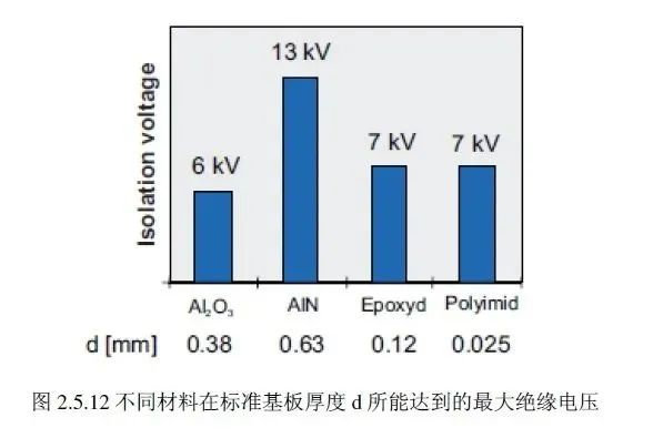
The advantage of ceramic substrates is that their thermal expansion coefficient is very close to that of silicon. In contrast, the expansion coefficients of metal materials (copper, aluminum) on IMS substrates (insulated metal substrates) are very different. When the temperature changes, stress will be generated between the substrate and the soldered silicon chip. After the IGBT module is connected, this stress will be aggravated, which will put higher requirements on the insulation and voltage resistance of the isolation material. Insulation and voltage resistance are related to many factors, such as substrate thickness, material and material uniformity, package shell and filler, and even chip placement. The insulation voltage of the materials currently used in modules is generally between 2.5 kVeff and 9 kVeff. Figure 2.5.12 shows the maximum insulation voltage that can be achieved for different materials currently used at standard substrate thickness.


