IGBT module/IPM Dead Time Design Method
Regarding the design method of dead time, the formula TD'=TD-(t3+t4)+(t1+t2) is transformed to TD=TD'+(t3+t4)-(t1+t2)=TD'+(t3-t1)+(t4-t2). The rest is how to define the delay of the driver board (t1, t3) and the IGBT delay (t2, t4). The design method is divided into these two parts, the dead time of the IGBT part and the dead time of the HIC part. (1) Dead time of the IGBT part ① Collection of error data of IGBT switching time and calculation of maximum error data Based on the IGBT data of each company, calculate the error data of IGBT switching time (Tj=25℃). Based on σ and X±4σ, calculate X±4σ of each IGBT. (Maximum error) The following is the σ value of Fuji IGBT for reference. ○600V series σ=0.041 (maximum)

② Calculation of switching time ratio when the junction temperature is 25℃ and 125℃

※σ is the maximum value of 0.063 recommended by Fuji.
③ Calculation of switching time when the junction temperature is 125℃
By multiplying the results of ① and ②, the switching time when the junction temperature is 125℃ can be calculated.
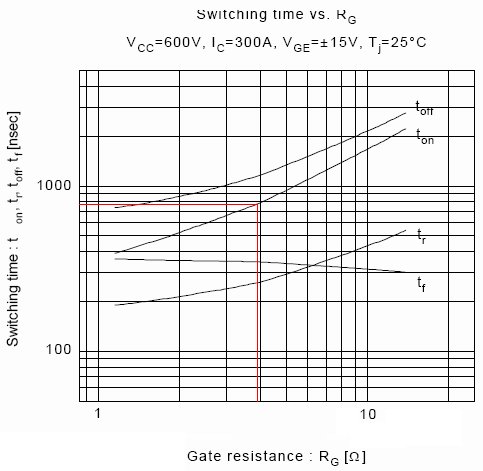
④ Calculation of the ratio of Rg and Vge under driving conditions
Since the conditions (Rg, Vge) of the data given in the data sheet are different from the conditions of the actual inverter drive, it is necessary to calculate the switching time ratio under the actual IGBT drive conditions.
⑤ Calculation of corrected switching time
 Here, the ratio of Rg and -Vge is obtained through the characteristic curves of Rg-Ton, Toff and -Vge, Ton and Toff. The data obtained from Table 1 above is multiplied by these two ratios to obtain the data in this table, such as 0.568×1.205×0.828=0.567. ⑥Calculation of IGBT dead time From the switching time of ⑤, toff (max)-ton (min) can be obtained. So far, the dead time of the IGBT part has been obtained.
 (2) Design method of HIC dead time of driver board ① The calculation of switching time at ambient temperature of 25℃ and maximum temperature is illustrated by taking M57962AL as an example. The switching time data at various temperatures are shown in the following table.
 ② The dead time of the HIC of the driver board is designed to be 60℃. When the ambient temperature is 60℃, the dead time is Td(HIC)=tpHL(max)- tpLH(min). Therefore, according to the above data, Td(HIC)=1.5- 0.3=1.2(uS) (3) Calculation of the total dead time After calculating the dead time of the IGBT part and the dead time of the HIC part, the total dead time can be calculated.


