
Typical IGBT Short-circuit Protection Circuit
1. Short-circuit protection circuit with increasing UCE when detecting short circuit
Figure 5-14 shows a protection circuit based on the principle that UCE increases when IGBT is overcurrent. The circuit uses the IGBT dedicated driver EXB841. The internal circuit of EXB841 can well complete the gate voltage reduction and soft shutdown functions, and has an internal delay function to eliminate false operations caused by interference. If a short circuit occurs, UCE containing IGBT overcurrent information is not directly sent to the IGBT collector voltage monitoring pin ⑥ of EXB841, but quickly turns off the fast recovery diode VD1, so that the U+ voltage of the comparator IC1 (LM339) is greater than the U- voltage, and the comparator outputs a high level, which is sent to the ⑧ pin of EXB841 by VD1, starting the gate voltage reduction and soft shutdown circuit in the internal circuit of EXB841, and the low-speed cut-off circuit slowly turns off the IGBT. This not only avoids the collector current spike from damaging the IGBT, but also completes the IGBT short-circuit protection. The characteristics of this circuit are that it eliminates the difference in shutdown speed caused by the different forward voltage drop of VD1 with different currents, improves the accuracy of current detection, and directly utilizes the gate voltage reduction and soft shutdown functions in the internal circuit of EXB841, so the overall circuit is simple and reliable.

2. Short-circuit protection circuit using current transformer to detect IGB1' overcurrent
Figure 5-15 shows a short-circuit protection circuit using current sensor to detect IGBT overcurrent. The primary (1 turn) of the current sensor (SC) is connected in series in the collector circuit of the IGBT. The overcurrent signal sensed by the secondary is sent to the non-inverting input terminal of the comparator IC1 after rectification. After comparison with the reference voltage at the inverting terminal, the output of IC1 is sent to the comparator IC2 with positive feedback, and its output is connected to the output control pin ⑩ of the PWM controller UC3525. When there is no overcurrent, the potential at point A UA<uref, the potential at point b ub=0.2v, the potential at point c ucUref, and UB is high level. At this time, C3 is charged through R1. After a certain delay, UC will be greater than Uref, IC2 outputs a high level, and the EXB841 protection circuit works, causing the IGBT to reduce the gate voltage and softly shut down. After the IGBT is turned off, no current flows through the primary of the current transformer, making UA less than Uref again, UB returns to about 0.2V, and C3 discharges through R1. When Uc<uref, IC2 outputs a low level and the circuit re-enters the working state. If the overcurrent continues to exist, the protection circuit returns to the original current limiting protection working state, and the cycle is repeated, so that the output drive waveform of EXB841 is in an interval output state, and the effective value of the IGBT output current is reduced, thereby achieving the purpose of protecting the IGBT. Potentiometer RP1 is used to adjust the overcurrent action threshold of the IC1 comparator. Capacitor C3 can be quickly charged through VD5 and R5, and slowly discharged through R1. As long as the parameters of R1, R5 and C3 are reasonably selected, EXB841 can be realized to close the IGBT relatively quickly and restore the IGBT relatively slowly. The positive feedback resistor R7 ensures that the IC2 comparator has a hysteresis characteristic, and together with the R1 and C3 charging and discharging circuits, it ensures that the output of IC2 does not frequently change between high and low levels, causing the IGBT to be frequently turned on and off and damaged, thereby improving the reliability of the circuit. < p="">

3. Comprehensive short-circuit protection circuit using the principle of UCE increase when IGBT is short-circuited and current transformer overcurrent detection
Figure 5-16 shows a comprehensive protection circuit using the principle of UCE increase when IGBT is short-circuited and current sensor detection.
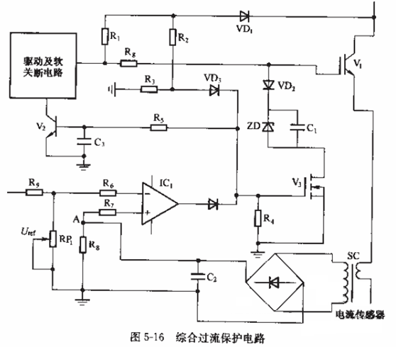
The working principle of this circuit is: when the load is short-circuited (or the IGBT is overcurrent due to other faults), the UCE of the IGBT will increase, VD1 will be turned off, and the current provided by R1 will be divided by the voltage divider R2 and R3 to turn on V3, so that the gate voltage of the IGBT is limited by ZD and the voltage is reduced, limiting the amplitude of the IGBT peak current. The voltage is delayed by R5 and C3 at the same time to turn on V2 and output a soft shutdown signal. In order to improve the reliability of the short-circuit protection circuit, the short-circuit current is detected by the current sensor during a short circuit, and the high level output by the comparator IC1 turns on V3 to reduce the gate voltage, and V2 turns on to perform soft shutdown protection of the IGBT.
