
IGBT module NTC temperature sensor resistance and temperature measurement
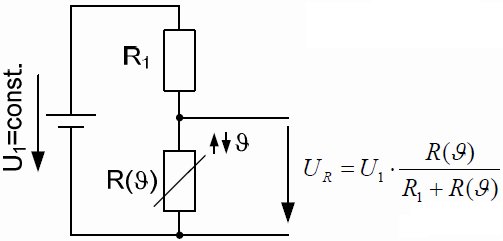
1. Use analog circuit to measure the temperature of IGBT module NTC temperature sensor: This basic method is based on a voltage divider as a thermistor, as shown in the figure below:
NTC characteristics are in two different formats in the data sheet, one graphical format R=f(θ), which can approximate the analytical description of all parameters of the graph. The valid mathematical expression is as follows:
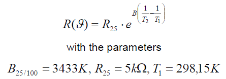
For more accurate calculations, if focusing on a smaller temperature range, the data sheet also provides the values of B25/50 and B25/80.
Based on the known measured UR, the actual resistance R (θ) can be calculated as follows:
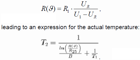
If there is an expected value for the temperature, the equation can be easily processed by a microprocessor, using the digital UR as input.
If only a maximum temperature is needed as a threshold signal, it is sufficient to use a comparator that triggers a predetermined value.
Provision of the voltage divider resistor R1:
The selection of R1 needs to be done carefully to obtain a correct reading. If it is chosen too small, the flowing current inside the NTC will cause losses and thus heat up the device, thus falsifying the measurement result. On the other hand, if R1 is chosen too large, the measured voltage will become too small and the measurement accuracy will decrease again.
In order to minimize the influence of the current, the thermal diagram is helpful. The thermal conductivity of the NTC is 145K/W. If an influence of 1K can be tolerated, the power dissipation inside the NTC must not exceed Pmax=6.9mW.
Assuming that measurements up to 100°C are required, the NTC will reach a value of R100=493. From this, the maximum current can be calculated as
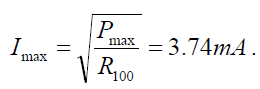
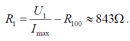
When the power supply voltage U1=5V and the current limit is 3mA, the resistor R1 becomes:
Since there is no such resistor, 910 can be selected, resulting in Imax=3.56mA; as long as the difference of 1K is tolerable, the current can be considered to be limited to any value of I<4mA.
2. Digitally measure the temperature of the IGBT module NTC temperature sensor:
In addition to using a voltage divider, the change of NTC resistance with temperature can be used to affect the time constant of an RC network, as shown in the following figure:
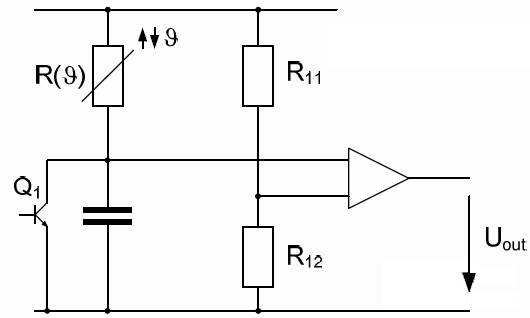
Resistors R11 and R12 determine the threshold for the comparator to change the output state. The output signal voltage Uout is used to trigger transistor Q1 to discharge the capacitor. The capacitor is charged through the NTC resistor R (θ), and Uout works in pulse mode with a certain frequency fout = g (θ).
In order to reconstruct the actual temperature based on Uout, it is sufficient to use the pulse count within a specified time period. The number of pulses represents the temperature value, and the mapping of the number of pulses to the temperature can be described analytically or interpolated between the two closest values.
