IGBT parallel connection technology-classification of parallel connection methods
IGBT parallel connection can be divided into two categories: "hard parallel connection" and "bridge arm parallel connection".
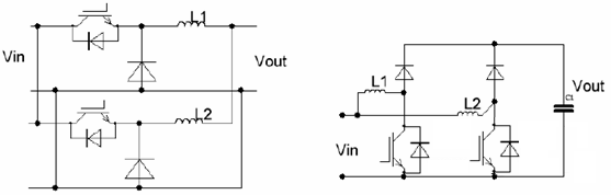
(1) "Hard parallel connection" means that the emitter and collector of IGBT are directly connected together, as shown in the lower left figure;
(2) "Bridge arm parallel connection" means that the AC output terminals of the IGBT bridge arms are connected together through a current-sharing reactance (the inductance has a certain value), as shown in the lower right figure;

Bridge arm parallel connection: Bridge arm parallel connection is a relatively low-risk parallel connection technology;
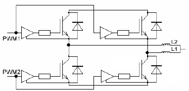
Characteristics of the hardware circuit: (1) The outputs of the two bridge arms are first connected to a current-sharing reactance, and then the currents are pooled together;
(2) Two IGBTs connected in parallel cannot share an IGBT driver and must use independent IGBT drivers;
(3) The input PWM signal of the driver must be sufficiently synchronous.
Analysis of the commutation circuit in the IGBT bridge arm parallel topology: In the circuit topology of the IGBT bridge arm parallel connection, the two bridge arms have their own independent commutation circuits, and there will be no exchange of current between the two bridge arms.
Specifically: (1) If Q2 is turned on when D1 is freewheeling, reverse recovery occurs in D1, and all the reverse recovery current flows into Q2 and will not go to Q4, as shown by the red line in the figure below;
(2) If Q2 is conducting current, when Q2 is turned off, all the current will be freewheeled by D1 and will not flow to D3. The reason is that there are two reactances L1 and L2 between the two bridge arms, so the dynamic impedance between the two bridge arms will be relatively high. The high-frequency current in the dynamic process of commutation cannot flow from one bridge arm. He ran to another bridge arm and was blocked by the reactance.
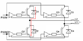
Conclusion: There is no risk of dynamic current sharing in this parallel method. The commutation behavior of each bridge arm is performed independently.
There is a very important premise for the above proposition to be established, that is, the values of L1 and L2 must be large enough, at least enough to block the commutation behavior between the bridge arms.
Analysis of current sharing reactance in IGBT bridge arm parallel topology: In IGBT bridge arm parallel topology, the output impedance of each bridge arm will determine the distribution of the effective value of the output current. In the figure below, the current sharing reactances L1 and L2 belong to the left side respectively. Bridge arm and right bridge arm, it is obvious that the main body of the output impedance of the bridge arm is the inductive reactance of the current sharing reactance, while the impedance of the IGBT bridge arm itself can be ignored compared with the inductive reactance.
Therefore, the output level of the two bridge arms (or the overall current sharing level) is mainly determined by the inductance of the current sharing reactances L1 and L2. If the inductance is too large, the output current of the corresponding bridge arm will be small; if the inductance is too small, the output current of the corresponding bridge arm will be too large.

Conclusion: The overall current sharing situation of the bridge arm is determined by the ratio of the inductive reactance of the bridge arm's current sharing reactance.
In this kind of circuit, the manufacturing process of the reactance is critical, and the deviation level of the inductance will determine the static current sharing level of the bridge arm. The risk of circuit current sharing is transferred to the reactance.
Analysis of drive signal synchronization in IGBT bridge arm parallel topology: In IGBT bridge arm parallel topology, the PWM signal is required to be sufficiently synchronized, and the concept of "synchronization" here needs to be quantified. Use a very specific way to describe the degree of signal synchronization.
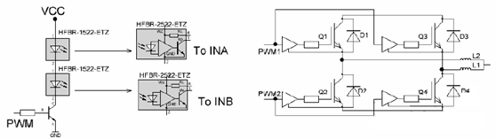
In this application, the synchronization requirements are relatively low, and it does not need to reach nS level, but a hundred nS level is enough.
As shown in the picture below on the left, two optical fiber light-emitting heads are lit by the same current, and then the signal is transmitted to INA and INB. We can say that these two signals are "synchronous", but in fact, the light-emitting head, optical fiber path, and receiving head In theory, there is a time difference. In the worst case, there should be a difference of several hundred ns or even more than 1us. However, in parallel arm applications, this is perfectly acceptable. This difference can be ignored in engineering.

The selection principle of the current sharing reactance in the IGBT bridge arm parallel topology: The selection of the value of the current sharing reactance is very important, because the cost of the reactance is not low. If the inductance is too large, the cost will go up, and heat dissipation is also a problem. Therefore, the principle for selecting current-sharing reactance is: on the premise of meeting the current-sharing performance, the inductance should be as low as possible. (1) The greater the inductance of the current-sharing reactance, the weaker the coupling between the bridge arms, and the less likely it is for circulating current to occur;
(2) The better the structural symmetry of the bridge arm, the lower the requirement for current sharing reactance inductance;
(3) The better the PWM pulse synchronization of the two bridge arms, the lower the current sharing reactance inductance requirement;
(4) The better the consistency of the drive circuit (such as the gate voltage value), the lower the current sharing reactance inductance requirement;
(5) The determination of the specific sensing value depends largely on experiments. Possible values will range from a few uH to hundreds of uH, depending on the application.
Other examples of IGBT bridge arm parallel applications: The figures below are examples of Buck circuits and Boost circuits, both of which use bridge arm parallel connection. Both methods are relatively common in practice. However, the main purpose of the reactance in these two applications is not for current sharing, but for the ripple level of the output voltage, so there are other constraints on the selection of the inductance.