DOUBLE PULSE TEST OF IGBT
(1) The Significance Of IGBT Double Pulse Test
l Compare the parameters and performance of different IGBTs;
l Obtain the parameters of the IGBT turn-on and turn-off process;
l Evaluate whether the driving resistor is suitable;
l Whether there is inappropriate oscillation during the turn-on and turn-off process;
l Evaluate the reverse recovery behavior and safety margin of diodes;
l Whether the voltage spike when the IGBT is turned off is appropriate, and whether there is inappropriate oscillation after turning off;
l IGBT turn-on and turn-off time;
l Measure the stray inductance of the busbar.
(2) Principle Of Igbt Double Pulse Test
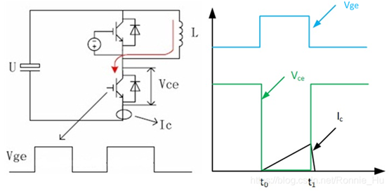
The so-called IGBT double-pulse test means that the upper tube is continuously turned off and the lower tube driving signal is given two pulses to test the switching characteristics of the IGBT. An inductor is connected in parallel to both ends of the upper tube. The main test is the characteristics of the lower tube and the reverse diode characteristics of the upper tube.
1) At time t0, the gate emits the first pulse, the lower bridge IGBT is saturated and turned on, the voltage U is applied to both ends of the load L, and the inductor current rises linearly.

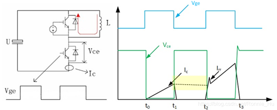
1) At time t1, the lower bridge IGBT is turned off, and the inductor current freewheels from the upper bridge diode. The current waveform is shown as a dotted line. Since the current probe is placed on the emitter of the lower bridge, when the upper bridge diode freewheels, the current probe detects less than this current.

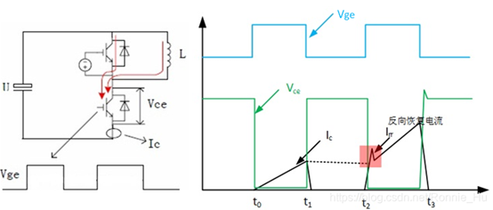
1) At time t2, the rising edge of the second pulse arrives, the lower bridge IGBT is turned on again, and the upper bridge freewheeling diode reversely recovers. The reverse recovery current will pass through the lower bridge IGBT, and this current can be captured on the current probe. At this moment, focus on observing the opening process of IGBT. The diode reverse recovery current is an important monitoring object, and the shape of this current directly affects many important indicators of the commutation process.

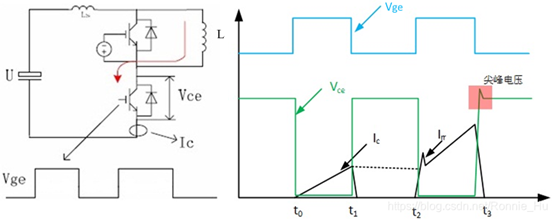
1) At time t3, the lower bridge IGBT is turned off again. At this time, the current changes greatly. Due to the existence of bus stray inductance Ls, Vce will generate a certain voltage spike. At this moment, focus on observing the IGBT turn-off process. Vce voltage spike is an important monitoring object, and it is also necessary to pay attention to whether there is inappropriate oscillation in voltage and current after shutdown.


