EFFECT OF TEMPERATURE CHANGES ON MODULE LIFE
Thermal cycling changes within all power modules cause module aging. The reason is that the thermal expansion of the materials used is different, so the thermal stress between them can cause connection fatigue or even breakage. The service life of the module and the number of cycles it can withstand temperature changes will decrease as the amplitude T of the temperature change increases. In the frequency range from a few Hz to a few hundred Hz, the change in power consumption is not caused by the transient thermal impedance of the chip. It only causes a small temperature fluctuation of the module chip. Although at this frequency, T is not so small and has low energy, it will be absorbed by the elastic filler and has little impact on the aging of the module. It has no impact on the service life. When working at a few hertz, and the load changes in the range of a few seconds and generates high temperatures, such as traction drives, elevators and intermittent pulse applications, the temperature change load effect will occur inside the module, which will affect the connection belt inside the module. To test, these connections are:
- Wire connection
- Soldering on the bottom of the chip
- Welding of DCB base plate and base plate
- Welding of metal and ceramic sheets (copper on Al2O3 or AlN board)
Research must be done in the thermodynamic calculations to see if Tj is large enough to cause us to fall short of the design requirements. At this time, during the observed load cycle, the temperature difference Tj =Tj(max) -Tj(min), what we use at this time is not the maximum temperature Tj (maximum value) of the module.
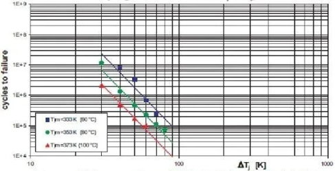
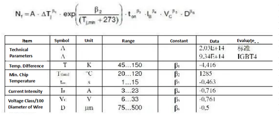
The relationship between the number of load cycles n and the temperature change amplitude TJ depends on many factors and is extremely difficult to measure. In the late 1990s, a research institution produced the first research results, which revealed the dependence of the average temperature Tjm on temperature changes. Using a parameter to integrate and adjust the parameters A, α and the injection energy Ea, the result is that the service life satisfies the following formula:

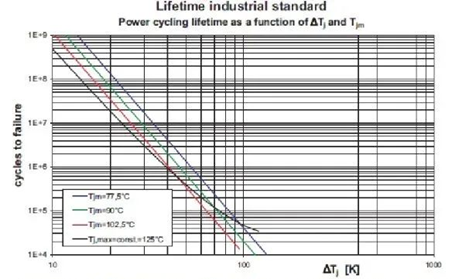
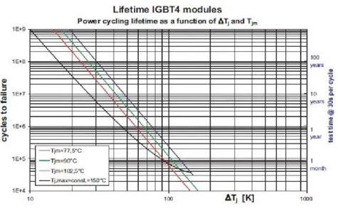
As shown in the figure, when Tj is greater than 30 K, the number of load change cycles decreases by ten percent for every 20 to 30 K increase in temperature change amplitude. These temperature amplitude variation curves below 30K need to be considered when the variation period is in the range of seconds to minutes. These curves were obtained by testing modules produced by different manufacturers and are given as technical standards. Nowadays, structural design and manufacturing processes have been improved, so today's semiconductor modules can achieve higher load cycles.


This curve takes into account the effect of average temperature or temperature changes at that level. However, many test results show that parameters such as pulse width ton and current amplitude IB have an impact on the test results. Similarly, parameters in AVT such as the strength and angle of the wire and the thickness of the chip and soldering layer will also have an impact. . After evaluation in various tests, an extension model has been proposed. Its parameters and valid limits and constants are listed in the table below:

For example: If the number of load cycles of a component is Nf, the test cycle is ton (Test), and the pulse width is ton (Anwendung), the result is:
That is, when the applied pulse width is 1/10 of the test cycle, the service life is increased approximately three times. This model gives a way of thinking about the impact of various parameters on the load change number. Because of the limitations of physical parameters, its role in accurately calculating service life is limited after all, because not all parameters are independent. For example, it is not possible to generate a small TJ and wide pulse in large currents. Or, for example, when the pulse width is constant, for the same TJ, different experimental periods ton require different large currents.


