DEFINITION OF STRAY INDUCTANCE INSIDE IGBT MODULE
The working principle of the IGBT half-bridge inverter circuit and the voltage and current waveforms when IGBT1 is turned on and off are shown in Figure 1. Lσ represents the sum of all stray inductances (capacitors, busbars, IGBTs) in the entire commutation circuit (within the stripe area) module).
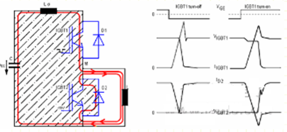
Figure 1: IGBT half-bridge circuit and voltage and current waveforms when IGBT1 switches
Due to the change in current, a voltage drop of Lσ*dioff/dt is induced across the stray inductance Lσ. This voltage drop is regarded as a voltage spike superimposed on the DC bus voltage VCC and is simultaneously applied to both ends of the turned-off IGBT1. end. The allowable limit current turn-off speed di/dt and overvoltage capability can be derived from the IGBT's RBSOA (reverse bias safe operating area) curve (Figure 2). This curve is valid if the measurement is through the auxiliary CE terminal of the IGBT. If the measurement is performed on the main terminal of the IGBT module, taking into account the stray inductance between the main terminal and the auxiliary terminal, the derating curve will be given accordingly in the specification book. For an IGBT two-unit module, this figure shows the voltage across one of the two commutation IGBT switches.
The stray inductance value Ls inside the IGBT module will be given directly for calculation. For a single switch IGBT module, the value of Ls is the stray inductance between the main terminal and the auxiliary terminal of the module. For two-unit IGBT modules or IGBT modules containing multi-phase bridge arms, the value of Ls depends on the effective commutation loop between the corresponding upper and lower tubes in the application. According to the structure of the IGBT module, this value will be significantly smaller than the sum of stray inductances determined respectively by the upper tube and the lower tube. In a module with more than a single phase leg, the commutation circuit from a positive supply voltage, through that phase leg, back to a negative supply voltage is always the worst case scenario.
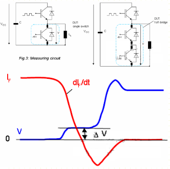
The internal stray inductance can be measured by turning off the diode. At a certain moment, when the diode's forward current decrease rate remains constant and the diode still has no blocking ability, a voltage drop occurs across both ends. This voltage drop can only be caused by the stray inductance of the module and has no other influencing factors. Module stray inductance can be obtained by the following formula: Ls=△V/diF/dt.