
PARALLEL USE OF IGBTS
Using IGBTs in parallel to form switching devices can enable the entire system to obtain a higher rated current. However, some important issues must be considered when designing a parallel system, such as module characteristics, drive circuits and circuit layout. These factors affect the current distribution of parallel branches. This may result in uneven current distribution for each IGBT connected in parallel. Among them, the volt-ampere characteristics in the module characteristics mainly affect the current distribution during static operation, and the transfer characteristics, drive circuit and layout mainly affect the current distribution during dynamic operation. Due to the imbalance of current distribution, the rated current of n IGBTs connected in parallel is not equal to n times the rated current of a single module, so the parallel IGBT modules must be derated.

When designing an IGBT parallel system, you must first determine the appropriate number of parallel modules to obtain sufficient rated current, and at the same time ensure that each module does not exceed the safe operating area when operating. It should also be noted that using IGBT modules in parallel can help reduce on-state losses, but switching losses will not be reduced and may even increase, especially when the switching frequency is relatively high.
(1) Parallel operation static current sharing
Under static conditions, the current distribution between IGBTs working in parallel is mainly affected by the volt-ampere characteristics. When multiple IGBTs are connected in parallel, the volt-ampere characteristics of each IGBT are not exactly the same due to the manufacturing process. The influence of volt-ampere characteristics on current distribution when two IGBTs are connected in parallel is shown in the figure. It can be seen from the figure that when two IGBTs with different volt-ampere characteristics work in parallel, the currents flowing through them are not equal. In order to ensure that each module does not exceed the safe working area during operation, the IGBTs running in parallel must be derated. If two tubes of the same model but with different volt-ampere characteristics are used in parallel, their total rated current is not equal to twice the rated current of a single tube. This coefficient of current capacity reduction can be called the current derating coefficient. The current derating factor can be expressed as
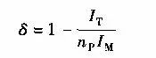
In the formula, IT is the total rated current that parallel modules can provide; IM is the maximum rated current of a single module, np is the number of parallel modules. For example, if two IGBT modules with a rated current of 400A are connected in parallel, one withstands a current of 400A and the other with a current of 320A, you can get

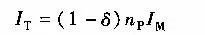
Additionally, if the derating factor is known, the total rated current provided can be found from
(2) Dynamic current sharing in parallel operation
Under dynamic conditions, the current distribution between IGBTs working in parallel is mainly affected by the transfer characteristics and drive circuit.
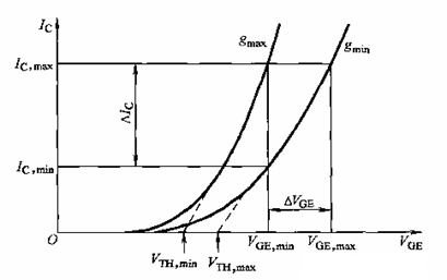
1) The impact of transfer characteristics on dynamic current sharing: When IGBTs with different transfer characteristics are connected in parallel, the dynamic current distribution during the switching process is unbalanced. The figure shows an example of dynamic current imbalance between two IGBTs with different transfer characteristics under the same VGE drive. It can be seen from the figure that tubes with steep transfer characteristics bear a relatively large dynamic current at the switching moment, so they will also have relatively large switching losses. This difference is more obvious when turning off. This imbalance tends to ease as the switching frequency increases. Selecting IGBT modules with similar transfer characteristics for parallel connection is beneficial to dynamic current sharing.
2) The impact of the drive circuit on dynamic current sharing: The impact of the drive circuit on parallel current sharing is also obvious. If the IGBT drive circuit working in parallel is not synchronized, the IGBT driven first will bear a much larger dynamic current. Therefore, the drive of parallel modules must be synchronized. It is best to choose a driver with strong driving capability and use the same drive signal to drive parallel modules at the same time.
In addition, the drive circuit layout should be as symmetrical as possible, and the gate and emitter leads from the drive circuit to the module should be as short as possible to make the equivalent impedance of the loop consistent; the component layout and lead positions in the main circuit should be symmetrical, and the lead lengths should be consistent , and be as short as possible. The wiring should use copper bars or flat wires with larger cross-sectional areas; the modules should be placed in parallel, as close as possible, and the leads should be as consistent as possible to reduce the imbalance of parasitic inductance in the loop.
