
Detailed Explanation of IGBT Module Parameters - Thermal Resistance Characteristics
The power dissipation and rated current of the IGBT module are meaningless regardless of the temperature and thermal resistance of the IGBT module. Therefore, in order to compare the performance of different power devices, it is necessary to analyze their thermal characteristics. The heat generated by the power loss of the IGBT module will increase the junction temperature inside the device, thereby reducing the performance of the device and IGBT converter and shortening its life. It is very important to dissipate the heat generated from the chip junction to reduce the junction temperature. The transient thermal impedance Zthjc(t) describes the heat dissipation ability of the device. The thermal resistance Rth is defined as the value of the junction temperature rise relative to the temperature of the external specified point caused by the unit power consumption when the silicon chip consumes power and reaches thermal balance. It is a key factor to measure the heat dissipation capability of the IGBT.
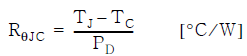
RθJC (junction to case thermal resistance): refers to the thermal resistance between the junction of each switch tube (silicon chip) and the shell (module bottom plate). This value depends entirely on the package design and internal frame material. RθJC is usually measured at Tc=25℃ and can be calculated by the following formula:
Tc=25°C is the condition of using an infinite heat sink, and the temperature of the shell is the same as the ambient temperature, the heat sink can reach Tc=Ta.
The IGBT module specifies the RΘJC values of the IGBT and the anti-parallel diode separately.
RΘCS (contact thermal resistance, case to heat sink): refers to the thermal resistance between the module base plate and the heat sink. This value is related to the package form, the type and thickness of thermal grease, and the installation method of the heat sink.
RΘSA (thermal resistance from heat sink to atmosphere): depends on heat sink geometry, surface area, cooling method and mass.
When characterizing the thermal characteristics of a power module or discrete device with a substrate, it is necessary to look at the temperature of the die junction, case, and heat sink.
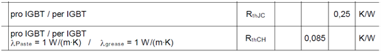
The thermal resistance specifications of the base plate and the thermal resistance from the base plate to the heat sink are shown in the figure below. The thermal resistance RthCH from the base plate to the heat sink defines a typical value under the specified thermal interface material conditions.
The thermal resistance Rth describes the thermal behavior of the IGBT module in a steady state, while the thermal resistance Zth describes the thermal behavior of the IGBT module under transient or short pulse current. Rth can only describe the DC operating mode. Most practical IGBT applications perform switching actions with a certain duty cycle. Under such dynamic conditions, it is necessary to consider using the method of thermal resistance and heating capacity to describe its equivalent circuit. The figure below shows the transient thermal impedance ZthJC as a function of time, with ZthJC(t) saturated when it reaches its maximum value RθJC.
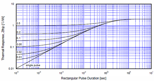
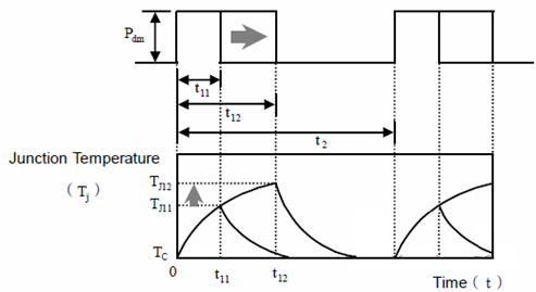
The single pulse curve determines the thermal resistance under continuous pulse operation with a certain duty cycle (D), as follows:

In the formula: Zthjc(t) is the continuous pulse transient thermal resistance with duty cycle D, Sthjc(t): single pulse transient thermal resistance
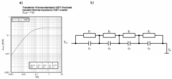
The power consumption of IGBT modules is mainly dissipated from the chip to the heat sink through different materials. Each material on the power dissipation path has its own thermal characteristics. Therefore, the thermal impedance behavior of the IGBT module can be modeled using appropriate coefficients, and the thermal impedance curve ZthJC(t) in Figure a above is obtained. The individual RC elements in Figure b have no physical meaning, their values are extracted from the measured module heating curves by corresponding analysis tools.
As shown in the table in Figure A above. The value of the capacitor can be obtained from the following formula:

The thermal resistance distribution and equivalent circuit diagram of the IGBT module are shown in the figure below:
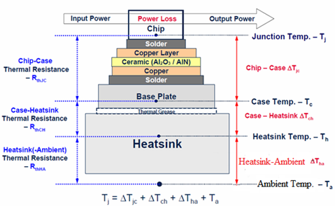
IGBT module thermal resistance and temperature distribution diagram
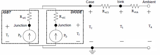
Assuming the heat sink is isothermal, then
Heat transfer is very similar to current transfer, obeying Ohm's law of heat circuit, and the equivalent circuit in the above figure can be used to describe the heat dissipation channel. The overall thermal resistance from the chip junction to the environment is represented by RθJA, and the equivalent circuit can be described by the following formula:

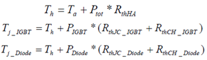
The relationship between the thermal resistance of one bridge arm of the IGBT module and the thermal resistance of the IGBT and diode in the bridge arm is as shown in the figure below:
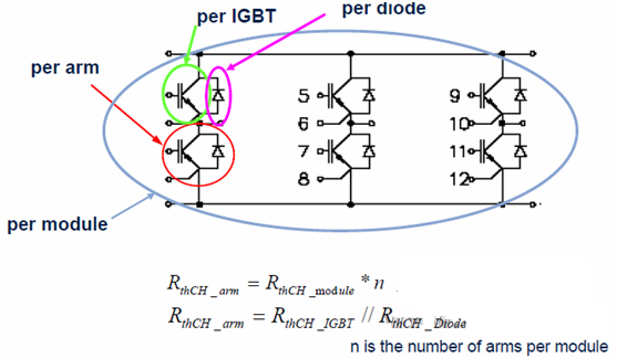
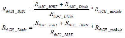
If the thermal resistance RthCH of the module is given, the thermal resistance of each IGBT and diode can be calculated by the following formula:
The figure below shows the simulation results of the IGBT junction temperature of the inverter at different operating frequencies:
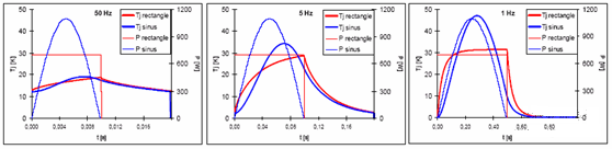
It can be seen from the figure above that even with the same power consumption, different operating frequencies will lead to large deviations in Tj. If you want to obtain detailed simulation results, you can use the simulation software of the device supplier to obtain them.
