
Safe operation of IGBT module/IPM
When the IGBT is turned off, the operating range of the VCE-IC that works safely is called the reverse bias safe operating area (RBSOA: Reverse Bias SafeOperation Area), also known as the switch safe operating area, which refers to the maximum allowable instantaneous voltage during repeated shutdown operation current. That is the range shown in Figure 1. When designing the snubber circuit, it is necessary to ensure that the working track of VCE-IC is fully accommodated in the RBSOA area when it is turned off. This RBSOA is divided into two regions during normal switching operation (solid line, round-trip) and during high current (short circuit) (dotted line, non-round-trip). For convenience, the area in the solid line is called RBSOA, and the area in the dotted line is called SCSOA (Short Circuit Safe Operation Area). Care should be taken since the SCSOA region tends to narrow as the collector current increases. The IPM has a built-in gate drive circuit and protection circuit to protect the operation mode beyond the safe operating area of the IGBT from damage to the module.
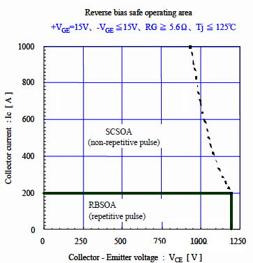
Figure 1 Reverse Bias Safe Operating Area (RBSOA)
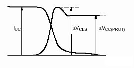
Figure 2 Switch safe working area (SOA)
IOC, VCES, VCC, if the three indicators do not exceed their specified values, then they are working in the safe working area.
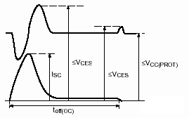
Figure 3 Short circuit safe working area (SCSOA)
As long as it meets the given technical indicators, it will generally not be damaged.
1. The requirements of the module itself on environmental parameters: safe working area
Do not exceed the specified maximum rating under any circumstances. For IPM, Vce<vces, ic<icp, tj<125°c, control power supply voltage vcc<20v, etc.
2. Select a device with the appropriate capacity.
3. Reasonable design (interface circuit and main circuit): reduce lead inductance, prevent mutual interference; use of fault terminal Fo.
4. Software design to prevent module damage: matching programming according to the characteristics of the application (load) to prevent abnormal currents at certain points;
The design of the dead time (tdead): greater than the recommended value in the specification (at the IPM terminal); the processing of Fo interruption and the control of the main circuit current, etc.
5. Power-on/off sequence problem: power-on is the control circuit first and then the main circuit; power-off is the opposite.
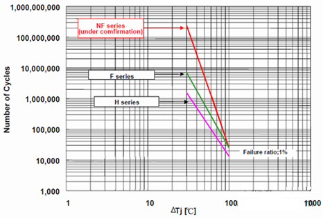
The power cycle life curve of the IGBT module is as follows:
The power cycle life curve of the IGBT module is as follows:
IPM (taking DIP IPM as an example) power cycle life curve is as follows:
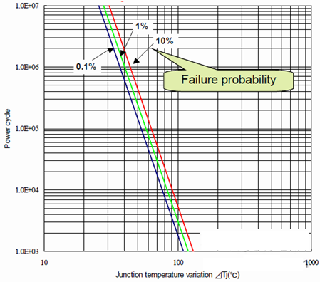
The junction temperature change ΔTj of DIP IPM has a very significant impact on the power cycle life. In order to ensure that the high power cycle has a low failure probability, it is necessary to avoid drastic changes in the junction temperature of the device.
Disclaimer: The content of this article comes from the Internet and is only for learning and communication. All opinions belong to the original author, which does not mean support or agreement with the opinions. If your rights are violated, please contact us in time to delete them.
