IGBT Quality Measurement Method- Quickly Teach You To Judge IGBT Quality
1. HOW TO MEASURE THE QUALITY OF IGBT
(1). First Determine The Polarity
Before measuring whether the IGBT is good or bad, the polarity of the IGBT must be determined first.
Set the multimeter to the R×1KQ position. When measuring with a multimeter, if the resistance value of one pole and the other two poles is infinite, and the resistance value of this pole and the other two poles is still infinite after changing the test leads, then it is judged that this pole is the grid (G).
Use a multimeter to measure the remaining two poles. If the measured resistance is infinite, the measured resistance becomes smaller after changing the test leads. When a small resistance value is measured for the first time, judge that the red test lead is connected to the collector (C), and the black test lead is connected to the emitter (E).
(2). The simple method - gate trigger
Short the 3 terminals together to discharge the IGBT. Do not touch any terminals during the test, keep the IGBT on the black case at all times.
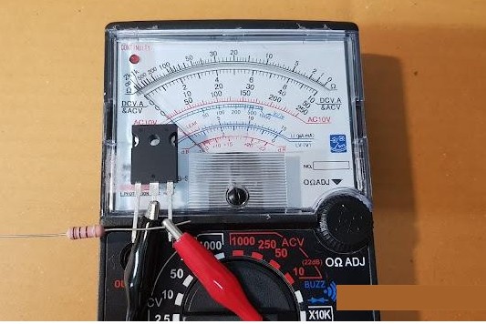
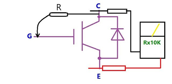
1) Take the smallest lead as a connection, then use a resistor to provide the trigger voltage from the C (collector) terminal to the trigger G (gate) terminal, a good IGBT will move the pointer of the multimeter forward and point to a certain resistor.
IGBT good or bad measurement diagram:
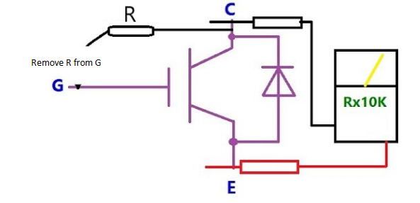
2) Then remove the resistor (trigger voltage), the IGBT still lets current flow and the pointer still points to the same position when the gate is triggered. After removing the trigger voltage, the pointer still points to the same position (it is a good IGBT), otherwise it is a bad IGBT.
IGBT good or bad measurement diagram:
2. DIODE FILE TEST--THE METHOD OF MEASURING THE QUALITY OF IGBT
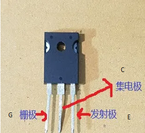
IGBT has 3 feet, which are G (gate), C (collector) and E (emitter). Its working principle is that the input voltage controls the output current. We can use this basic deviation to test whether it is a bad or good IGBT.
Important note: The analog multimeter used here is the version where the black test lead is V+ and the red test lead is V-, when it is set to the resistance test function.
(1) Analog Multimeter Test Igbt Good Or Bad
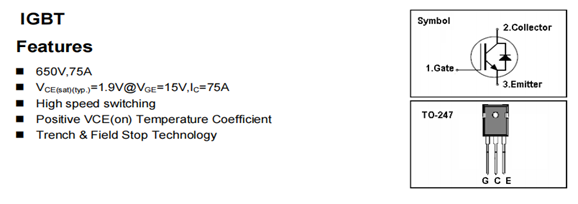
1) Get the IGBT pin diagram from the datasheet.
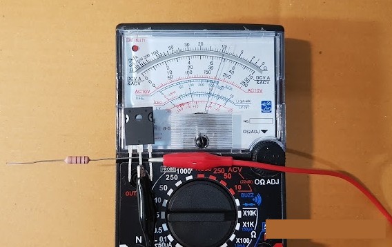
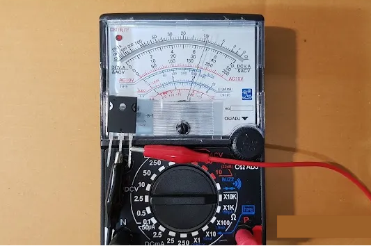
1) Connect the test wires to the pins of the IGBT, as shown in the figure below.
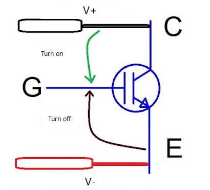
1) Set the analog multimeter to Rx10K as this range will be supplied with 9VDC from the internal battery. 9VDC is high enough to bias the gate so the IGBT is on.
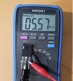
2) Temporarily connect the pin of the resistor between the G pin and the C pin, and move the pointer of the multimeter forward to the low resistance, as shown in the picture below.
1) After removing the resistor pin, the position of the pointer of the multimeter remains unchanged, because the IGBT is still working in the ON state, which means that the IGBT indicates good, but the bad IGBT cannot keep the ON state, so the pointer of the multimeter moves back to the ∞ position and removes the pin of the resistor back.
1) To test the OFF state, temporarily connect the G (gate) pin and the E (emitter) pin with a resistor pin. A good IGBT can be biased to both ON and OFF states, but a bad IGBT cannot be biased to both ON and OFF states.