What Do You Know About Triode
This time we expand the scope to NPN and PNP tubes, and give you some examples. The examples range from easy to difficult. If you can answer all of them, then you have a thorough understanding of triodes.
Regarding the NPN tube, the NPN triode, the voltage of 10V is applied to the base, and 100KΩ is connected in series to the base, so what is the base current flowing into the transistor?
It seems simple, but in fact, the inspection of the invisible and known conditions of the NPN triode is investigated, that is, there will be a 0.6V voltage drop between the BEs.
Then Ib=(10-0.6)/100KΩ=94uA
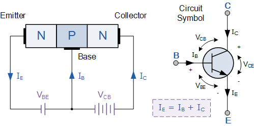
2 PNP transistors, for PNP transistors, it is better to remember that the currents of the three ports are reversed from the NPN.
NPN transistor: The current direction is from the base to the emitter (the driving current flows from the base), and the collector flows to the emitter.
PNP transistor: The current direction is from the emitter to the base (the driving current flows from the base), and the emitter flows to the collector.
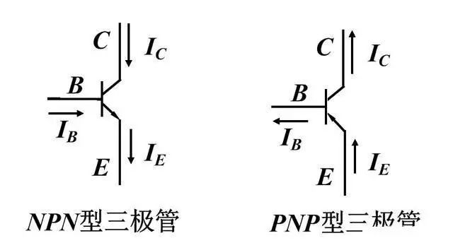
Of course, I don't particularly like this picture because the current direction of PNP flows from bottom to top, but in the actual circuit diagram, most of the emitters are still connected to high level. Special attention should be paid to this point. Comparing with the picture above will Better yet, the current is E to C anyway. Contrary to NPN tubes.
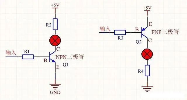
The comparative application of the two: NPN high level is turned on at B; PNP low level is turned on at B.
Therefore, pay attention to the tubes used during the analysis of the circuit diagram, and then analyze the logic for the tubes used.
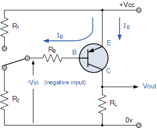
Combining PNP and NPN questions, it is said that this is a question that is often interviewed by power engineers. It examines most of the knowledge of triodes and the analysis ability of circuits. Given the following circuit: judge the voltage of V1. Give you 10 minutes to answer.
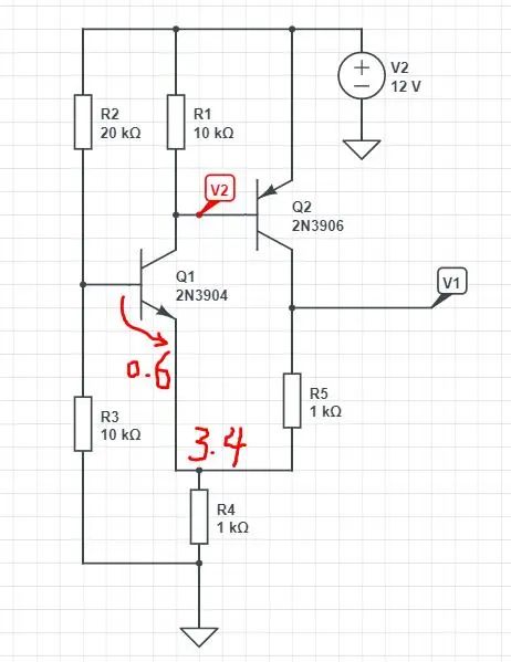
Step 1: First determine which devices are used in the picture. At first glance, there are NPN and PNP, so pay attention to the direction of conduction and the voltage drop of the diode. First look at the leftmost side, R2, R3 divide the voltage, then R3 is 4V, (assuming the BE conduction voltage drop of NPN is 0.6v), then R4 is 3.4V, and the current passing through R4 to ground is 3.4/1KΩ, 3.4 mA. I believe that at this point, most people can analyze it.
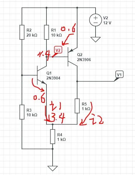
At this time, it depends on whether your understanding of PNP is deep enough. The breakthrough point is the voltage of V2. First, if Q2 is turned on, the voltage drop between EB is 0.6V, or this PNP clamps R1 at 0.6V. V. Then we know that the base voltage of Q2 is 12-0.6=11.4V.
Then the current passing through R1 is 0.6/10K=0.06mA=60uA. According to the node current above R4, 3.4mA-0.06mA=3.34mA. This is the current across R5.
Knowing the current of R5 also knows the voltage on R5: 3.4V+3.34mA*1KΩ=6.74V.
This is a very good example of combining N-type and P-type triodes. If you can solve this problem, the circuit analysis of the triode should not be a problem