The Most Typical Application of Triode-Mosfet Drive Circuit
To be honest, most of these circuits appear in interviews or textbooks to examine some people's understanding of triodes. But in the actual circuit, it is rare to see the triode working in the amplification area. Speaking of this, I also give reassurance to the college students in school. Every day in the textbook, "the collector is positively biased", and the "common collector and co-ejector" is very positive and that polar is reversed. To be honest, it is not very useful in work. If you do all these questions well, you will not be able to design an actual circuit; the engineer who designs the actual circuit may not necessarily be able to solve the problem.
So don't be intimidated by these diagrams. In practical applications, more triodes are used as logic or drive circuits, so it is enough to know more about their switching characteristics. Today, I will talk about a scene that is used more in actual cases, that is, the triode is used as the driving circuit of the mosfet:
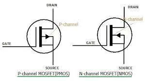
Put a picture of Pmos first, so that it is convenient to correspond to the names of each pole in the figure applied below. Ok, then we jump directly to the actual circuit below (assuming M1 is PMOS) R1 has a problem with the drawing here, please ignore that line.
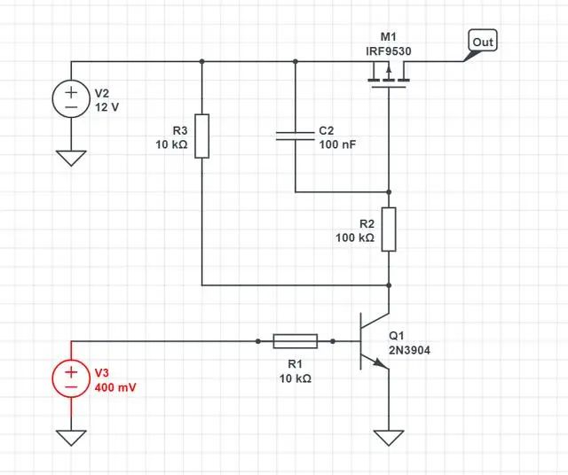
Let's take a look at the logic of this circuit first. When the base drive of the transistor Q1 is low, Q1 is not conducting, there is no voltage difference between the Vgs of the PMOS M1, and there is no voltage on the right side of M1; when the base drive of the transistor Q1 is high, Q1 is conducting, and the Vgs of the PMOS Close to -12V, M1 is turned on, and the right side is V2 input voltage 12V. Of course, by the way, write down the conditions for Pmos conduction, I know that many people will not remember:
The condition for PMOS (P-type metal oxide semiconductor field effect transistor) to be turned on is that its gate potential is lower than the source potential, forming a forward bias, so that a conductive electron channel is formed in the channel, thereby forming a drain-source extremely conductive path. When the gate potential of the PMOS is lower than a certain threshold voltage of the source potential, the resistance of the drain-source path will be significantly reduced, and the PMOS device will start to conduct. (Which is gate, source, drain compare to the picture above)
After understanding the principle, let's go a step further, how to value the resistors and capacitors.
First look at the connection to the Pmos gate
R2: For Pmos, the impedance on the gate is very large, so R2 can choose a larger resistance, and the current flowing through it here is very low anyway.
R3: Choose 10K, as a rule of thumb, when the triode is turned on, the current flowing through it is 12/10K=1.2mA. Here you need to go back and check the manual of the triode. 2N3904 finds that the current amplification factor is about 80, so Ib= 1.2mA/80=15uA.
R1: According to the current of Ib, it is easy to calculate the resistance value of R1. Assuming that the driving voltage of the triode is 3.3V, then R1 is (3.3-0.7)/15uA=173K.
We just said above that in most triode applications, we will not use the function of its amplification area at all.
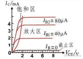
When Ic is known, according to the characteristic curve of the triode, the corresponding maximum Ib value can be obtained, that is, the critical value that makes the triode in the amplification region. If Ib exceeds this critical value, the triode may enter the saturation region, resulting in distortion of the output signal.
Then we want it to enter the saturation zone, so it is ok if R1 is smaller than 173KΩ, here we choose 10K.
Finally, let’s talk about why MOSFETs need triodes to drive. I haven’t seen an article about this. Maybe most engineers are also based on past rules of thumb.
In MOSFET switching circuits, using triodes as drive circuits can bring the following benefits:
Reduce the driving voltage requirements of the switching circuit: MOSFET requires a certain gate voltage to turn on, but in practical applications, the gate voltage needs to be boosted to a certain extent to reach the required voltage level. Using a triode as a driving circuit can increase the gate voltage to the required level through its voltage amplification function, thereby reducing the requirement for the driving voltage.
Improve switching speed and response speed: Using a triode as a driving circuit can provide a higher driving current, thereby speeding up the switching speed and response speed of the MOSFET, and reducing power consumption and loss during the switching process.
Improve switching efficiency and stability: Since the triode has a high voltage amplification factor and current amplification factor, it can provide stable current and voltage output, thereby improving the efficiency and stability of the switching circuit.
It should be noted that the use of triodes as MOSFET drive circuits also has some disadvantages, such as high complexity of the drive circuit and high power consumption, so it needs to be weighed and selected according to specific conditions in practical applications.
Finally, let’s talk about the function of C1. The mosfet is more sensitive like the triode. Here, in order to prevent misconduct, this RC is added.