
IGBT LIMIT VALUE
In the file data sheet, the limit values are given for each component of the IGBT module (IGBT, diode, housing, temperature sensor, etc.). All IGBT and diode limit values are given in a circuit (branch), regardless of how many transistor modules the circuit (branch) contains and whether the number of IGBT and diode chips is connected in parallel.
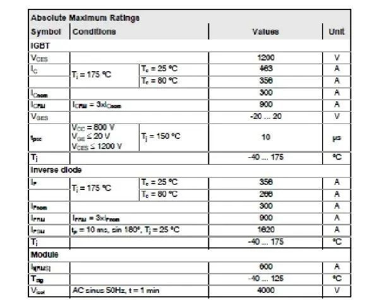
Collector-emitter voltage VCES It is the maximum allowable voltage between the collector and emitter of the IGBT chip when the gate and emitter are short-circuited and the chip temperature Tj = 25°C. Due to the relationship between breakdown voltage and temperature, the maximum collector-emitter voltage decreases with increasing temperature.
In any case, the sum of the operating power supply voltage VCC and the switch overload voltage VCE =Lσ·dic/dt is not allowed to exceed VCES (Lσ: the sum of parasitic inductances in the commutation circuit)
Collector DC current IC
It is the maximum DC current allowed by the collector when the chip temperature reaches the maximum allowable temperature. Condition parameters: For modules without base plate, case temperature TC = 25°C /80°C. For the module (SEMITOP) that can be soldered on the PCB board and at the highest PCB temperature, the heat sink temperature Ts =25 °C /70 °C. Chip temperature Tj = Tj(max).
For IGBT module IC with base plate, it is
IC = Ptot(max)/VCE(sat) where Ptot(max) = (Tj(max) – Tc)/Rth(j-c).
For modules without backplane, it is
IC = Ptot(max)/VCE(sat) where Ptot(max) = (Tj(max) – Ts)/Rth(j-s).
Because IC is a static maximum value, this parameter value should not be reached in practical applications.
Chip current ICnom
It is the typical data of this type of module given by the IGBT chip manufacturer (collector-DC current, maximum temperature limit at Tj (max)). For IGBT modules with multiple chips connected in parallel, a chip quantity factor must be multiplied.
Peak ICRM of periodic collector current
It is the peak pulse current allowed at the collector terminal. The ICRM given by the IGBT manufacturer on the data file is the peak collector current (collector pulse current, limited by Tj (max)), and their sum in the circuit must be multiplied by the number of parallel IGBT chips. This peak value has nothing to do with the width of the pulse. Even if the temperature of the chip does not reach the limit, this current peak value must be adhered to, because exceeding this peak value will cause metallization and premature aging of the chip. In many data file tables ICRM is written as 2 × ICnom, therefore, it is equivalent to the previous ICM limit value. For the example IGBT module chip, ICRM =3 X Icnom. At a given operating point of high gate resistance and high bus voltage, turning off such a large current will generate overvoltage and exceed VCES. Studies have shown that when such a large current is periodically turned off when the chip is hottest, the chip will exit the saturation zone early, resulting in large power consumption. It is for this reason that, except for special cases and special measures (such as reduction of bus voltage, active clamping, very slow turn-off process), the peak value is the same as that of its predecessor module in RBSOA, which is 2 · ICnom value . Some measures must take into account higher power consumption, especially when designing semiconductors.
