
IGBT Module Static Parameters
VCES: Collector-Emitter Voltage Of The IGBT
The highest allowable off-state collector-emitter voltage in the gate-emitter short circuit condition within the usable junction temperature range. In the manual, VCES is specified at a junction temperature of 25°C, and VCES will decrease as the junction temperature decreases. The relationship between the reduction range and the temperature change can be approximately described by the following formula:

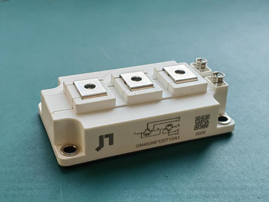
Due to the internal stray inductance of the module, the voltage difference between the main terminal and the auxiliary terminal of the module is as shown in the picture. Due to the internal and external stray inductance, VCES is most likely to be exceeded when the IGBT is turned off. VCES is not allowed to exceed under any conditions, otherwise the IGBT may be broken down.
Ptot: Maximum Rating For Ptot
Under the condition of Tc=25°C, the maximum allowable power loss of each IGBT switch, and the maximum allowable power dissipation through the junction-to-case thermal resistance. Ptot can be obtained by the following formula:

The maximum power dissipation allowed by the diode can be calculated by the same method.
IC nom: Collector DC Current
The maximum DC current flowing through the collector-emitter within the usable junction temperature range. According to the definition of the maximum power dissipation, the maximum allowable collector current can be calculated by the formula of Ptot. Thus in order to give the rated current of a module, the corresponding junction and case temperatures must be specified, as shown in the figure below. Note that current ratings are meaningless without specifying temperature conditions.

In the above formula, Ic, VCEsat, and Ic are unknown quantities, but they can be obtained in some iterations. Considering the tolerance of the device, in order to calculate the rated DC current of the collector, the maximum value of VCEsat can be used for calculation.
The calculated result will generally be higher than the manual value, and all values of this parameter are integers. This parameter only represents the DC behavior of the IGBT and can be used as a reference for selecting an IGBT, but it cannot be used as a measure.
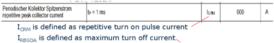
ICRM: Repeatable Peak Collector Current
The maximum allowable collector peak current (Tj≤150°C), the IGBT can exceed the rated current in a short time. It is defined in the manual as the repeatable collector peak current under specified pulse conditions, as shown in the figure below. Theoretically, if the overcurrent duration is defined, this value can be calculated from the allowable power dissipation and the instantaneous thermal resistance Zth. However, this theoretical value does not take into account the constraints of bonding wires, busbars, and electrical connectors. Therefore, the data sheet value is very low compared to the theoretically calculated value, however, it is the safe operating area specified considering the practical limits of the power module.
RBSOA: Reverse Bias Safe Operating Area
This parameter describes the safe working condition of the IGBT of the power module when it is turned off. If the maximum junction temperature allowed during operation is not exceeded, the IGBT chip can drive twice the rated current at the specified blocking voltage. Due to the stray inductance inside the module, the safe working area of the module is limited, as shown in the figure below. As the switching current increases, the allowable collector-emitter voltage needs to be derated. In addition, the derating of the voltage depends largely on the relevant parameters of the system, such as the stray inductance of the DC-Link and the commutation speed of the switching process. For this safe operating area, it is assumed that an ideal DC-Link capacitor is used, and the commutation speed is obtained under the conditions of specified gate resistance and gate drive voltage.
Isc: Short Circuit Current
The short-circuit current is a typical value. In the application, the short-circuit time cannot exceed 10uS. The short-circuit characteristics of IGBT are measured at the maximum allowable operating junction temperature.
VCEsat: collector-emitter saturation voltage
Under specified conditions, the saturation value of the collector and emitter voltage (the voltage drop of the IGBT in the on-state) when the specified collector current flows.

VCEsat increases with collector current and decreases with Vge. It is not recommended to use a too small value for Vge, as it will increase the conduction and switching losses of the IGBT.
VCEsat can be used to calculate the conduction loss of IGBT, as described in the following formula, the tangent point should be as close as possible to the operating point.
For the SPWM control mode, the conduction loss can be obtained by the following formula:
Disclaimer: The content of this article comes from the Internet and is only for learning and communication. All opinions belong to the original author, which does not mean support or agreement with the opinions. If your rights are violated, please contact us in time to delete them.
