
How to quickly check the fault of the IGBT module?
Due to the unbalanced output voltage of the frequency converter (VFD), the motor shakes and the speed is unstable. In general, it is difficult to determine which drive is at fault without experience. At this time, the 2hz of the VFD can be started, and the voltage values of p-u, p-v, p-w and u-n, v-n and w-n can be measured respectively with the DC voltage range of the multimeter. These six voltages will be different at this time, and the higher voltage will be different. The following is a simple measurement method for IGBT modules.
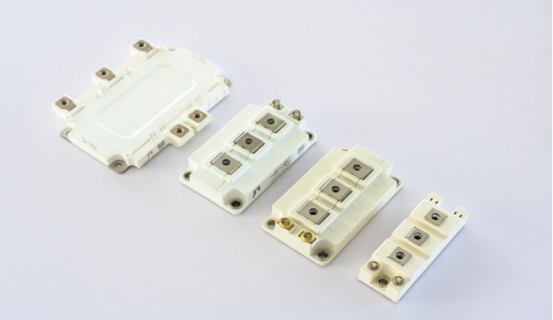
For the IGBT module, we introduce the simplest measurement method (this specialty does not measure it in this way), dial the digital multimeter to the diode test file, and test between the IGBT module c1, e1, c2, e2, and between the power grid G and e1, e2 The forward and reverse diode characteristics determine whether the IGBT module is intact. Take the six-phase module as an example. Remove the wires of U, V, and W phases on the load side, use a diode test file, connect a black stylus to P (collector c1), use a red stylus to measure U, V, and W in turn, and the multimeter will display infinite values; turn the probe upside down , The red probe is connected to P, the black probe measures U, V, W, and the multimeter shows about 400. Then connect the black stylus to N (transmitter e2), measure U, V and W with the red stylus, the multimeter shows about 400. The red stylus is connected to P, the black stylus measures U, V, W, and the multimeter displays infinite values. The positive and negative features of each stage should be the same. If there is a difference, the performance of the igbt module will be worse and should be replaced.
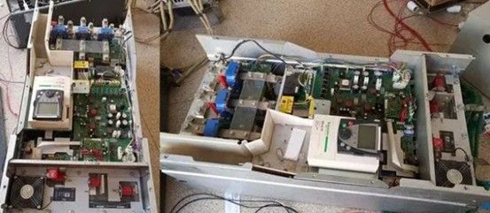
The following is an example maintenance case:
Maintenance process:
First disassemble the VFD completely, remove the heat dissipation channel radiator, clean the radiator with compressed air, and clean all the parts and boards inside the VFD. Install the igbt module. When installing the igbt module, install it in order according to the module requirements, with moderate torque. Repair the trigger circuit, and install the other devices in sequence. After installation, carry out static test. After the static test results are good, carry out the power test and load test. Pass the load test and complete the maintenance successfully.
Experience summary:
According to the maintenance status of several VFD modules in different models and different use environments, it is concluded that the main reason for the damage of the VFDigbt module is that the use environment is bad, resulting in damage to the electronic components on the access control card and blockage of the VFD heat dissipation channel. The most vulnerable components are voltage regulators and optocouplers. Check whether there is a problem with the drive circuit, and compare whether the resistance of each trigger terminal is consistent when the power is off. The voltage waveform at the trigger terminal can be measured by turning it on and off. However, some VFDs cannot be opened without loading the module. At this time, connect a dummy load to the P terminal of the module to prevent the module from being burned due to accidental contact with the starter or other lines during the inspection process.
