
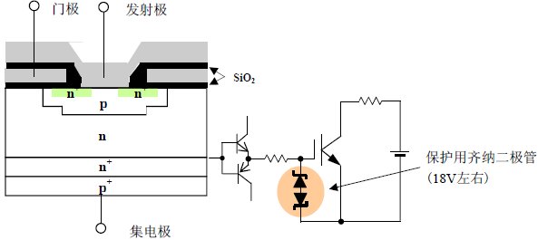
Gate driver for IGBT modules
Rated gate drive voltage: When the gate drive voltage is within the range of ±20V and a voltage exceeding this range is applied, the oxide film (SiO2) between the gate and emitter may be insulated and damaged, resulting in reduced reliability.
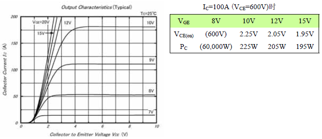
Turn-on gate drive voltage: The turn-on gate drive voltage standard is +15V. Low gate drive voltages such as 12V and 10V will increase electrode losses. At 6V, the IGBT is basically not turned on, and power is applied to the collector emitter. When such a low gate voltage is applied, it is possible that the component will be damaged due to excessive losses.
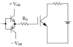
Gate reverse bias voltage (-VGE) during shutdown: To avoid malfunction due to noise interference, apply a reverse bias voltage of (-5V)-(-15V) to the IGBT gate during shutdown.
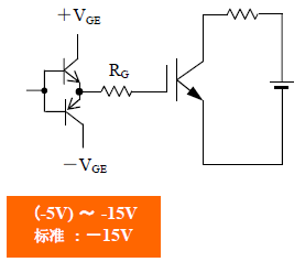
The relationship between the turn-on gate voltage, the gate reverse bias voltage at turn-off, and the switching speed-noise interference: If the turn-on gate voltage +VGE is increased, the turn-on speed will increase and the turn-on loss will decrease. On the contrary, the turn-on noise interference will increase. Similarly, if the turn-off gate voltage -VGE is increased, the turn-off speed will increase and the turn-off loss will decrease. On the contrary, the turn-off surge voltage and noise interference will increase. +VGE, -VGE and the next item RG are the main factors affecting the switching speed.
Gate impedance RG and switching characteristics:
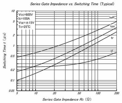
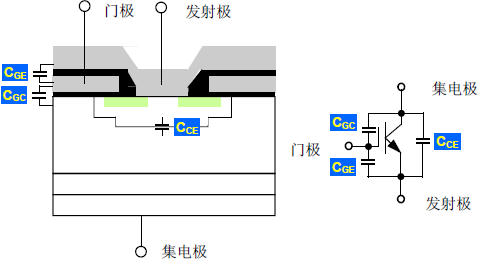
Gate capacitance: Input capacitance: Cies = Cge + CgcReverse transfer capacitance: Cres = CgcOutput capacitance: Coes = Cce + Cgc
Emitter-gate reverse bias voltage and gate-emitter impedance RGE: Due to high dv/dt, displacement current flows and the gate potential rises.
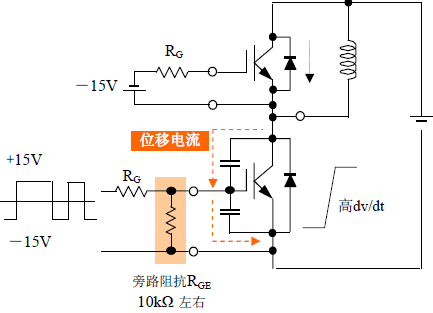
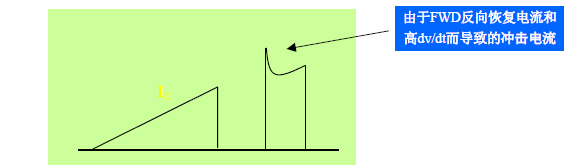
Gate reverse bias voltage and bypass resistor are effective in reducing inrush current (IGBT loss)
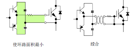
Gate wiring: To avoid harmful oscillation, please pay attention to the following. ● Keep gate wiring away from main circuit wiring as much as possible and avoid making them parallel. ● When crossing, cross them orthogonally. ● Do not bundle multiple gate wirings together. ● Adding common mode choke coils and ferrite rings can also achieve a certain effect.
Gate charging and drive current-power:
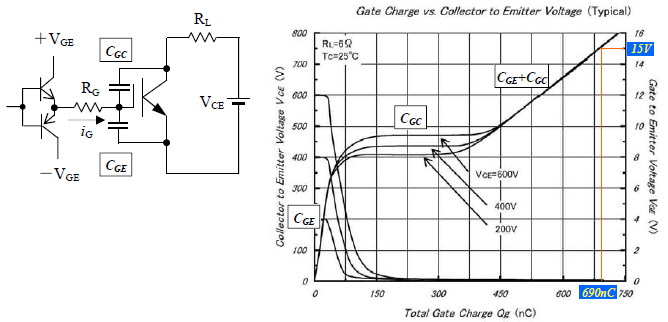
Calculation example of gate drive loss PG and maximum gate drive current iGP (+VGE=15V, -VGE=-15V, f=10kHz)PG={(+VGE)-(-VGE)}×Qg×f=30×690×10-9×104=0.207 (W)Assuming turn-on at 500ns; iGP = Qg / ton=690×10-9 / 500×10-9=1.4 (A)
