IGBT module three-level circuit failure shutdown sequence
The shutdown sequence of the IGBT module three-level circuit when it fails In the three-level circuit with a 1-shaped diode clamp, when a short circuit fault or overcurrent fault occurs, the traditional way to shut down the IGBT is that the driver that detects the fault transmits the fault information to the controller, and then the controller shuts down the outer tube first, and then the inner tube. The reason for this specific shutdown sequence is: 1. If the inner tube is turned off first by mistake, the inner tube IGBT will bear the entire bus voltage, so the inner tube will be severely over-voltage and immediately damaged; 2. If the outer tube is turned off first, the voltage of the outer tube will be clamped at half the bus voltage, and there will be no overvoltage, and then the inner tube will be turned off, and the inner tube will be safe.
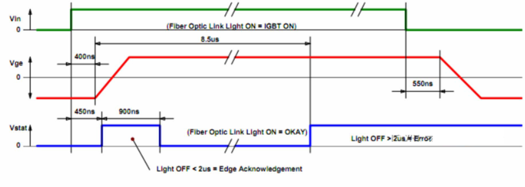
The timing relationship of the traditional shutdown sequence when the three-level circuit fails:

The figure above is a typical timing sequence of traditional fault management in a three-level topology. After the short-circuit response time has passed, the driver can confirm the fault to the controller, and it takes 2us for the controller to confirm the fault. In other words, by the time the controller confirms the fault, the short circuit has occurred for 10.5us (8.5us short-circuit response time + 2us confirmation time). This time is still the shortest time in theory, without considering the calculation time and transmission delay of the controller. Therefore, the short-circuit time in the three-level is generally slightly higher than 10us. Taking advantage of the active clamping function, the turn-off sequence of the 1-shaped three-level is ignored. When the IGBT detects a fault, whether it is the inner tube or the outer tube, the corresponding IGBT is immediately turned off, and then reported to the controller; if the channel that detects the fault is the inner tube, a shutdown command will be immediately sent to the inner tube IGBT, which will cause the inner tube IGBT to overvoltage, but in fact the inner tube IGBT cannot be turned off in this case, because the active clamping function clamps the inner tube voltage and no overvoltage occurs. In order to verify our innovative proposal, we conducted a series of verification experiments. Study on the effectiveness of active clamping in three-level circuits The following tests will study how the active clamping function protects the IGBT module in a three-level circuit in the event of an incorrect turn-off sequence. IGBT A certain 1-type three-level module; IGBT A certain driver equipped with active clamping function; The active clamping threshold (typical value of TVS breakdown) is set to 479V (1mA, 25℃); to support a maximum DC bus voltage Vdc of 870V (each half DC bus voltage is set to the same value for ease of measurement). Three different situations will be considered below: two short-circuit situations and a normal switching event, each with an "incorrect" turn-off sequence.
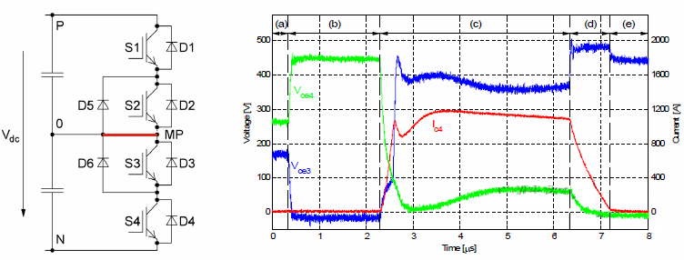
Experiment 1: Establish a short-circuit path between MP and 0

(a) All IGBTs are off, Vdc=870V; (b) S3 is turned on; (c) S4 is turned on, the short-circuit current increases rapidly, S3 is desaturated first, Vce3 rises to about 400V, Ic4 stabilizes at a certain level, and then S4 also desaturates;
(d) S3 is actively turned off first (according to traditional theory, S4 should be turned off first), S3 is restricted to the linear region by the active clamping function, and Vce3 is clamped at about 480V; IC4 (actually also IC3) drops to 0 with a slower di/dt, and the energy of all stray inductance in the loop is consumed in the linear region of S3, the IGBT; (e) The short-circuit current is 0, and the active clamping ends naturally; Experiment 2: Establish a short-circuit path between MP and P

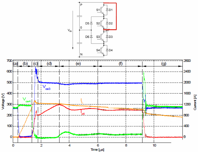
(a) All IGBTs are in the off state, Vdc=550V (b) S3 is turned on, and short-circuit current begins to appear. (c) S4 is turned on, Vce4 drops, D6 reverses and recovers and turns off, short-circuit current appears on S4, S3 desaturates, IC4 is lower than IL, which means that part of the short-circuit circuit is cut off and cannot be continued by D1 and D2. Therefore, Vce3 generates a voltage spike, which rises to 630V and is clamped to about 500V by the active clamp.
(d) S4 is still in the saturated conduction region. Because IL is greater than IC4, it means that D1 and D2 are conducting, and part of IL is continued by D1 and D2. (e) Vce4 begins to rise, that is, S4 begins to exit the saturation region. (f) The controller issues a command to turn off S3 (this is done intentionally to simulate the fault state). It can be seen that all physical quantities have not changed much. This is because the active clamp circuit has always been effective and clamps Vce3. It can be seen that the wrong shutdown sequence did not cause S3 to overvoltage;
(g) Turn off S4, the short-circuit current Ic4 is cut off, Vce4 generates a spike, but is also clamped by the active clamping circuit. When Ic4 is 0, the fault is resolved;
Experiment 3: Wrong commutation sequence

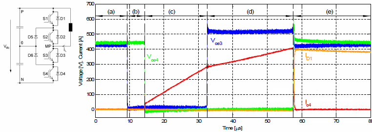
This experiment simulates the wrong commutation sequence in normal operation.
(a) All IGBTs are in the off state, Lload=65uH, Vdc=870V (b) Open S3 (c) Open S4, the load current rises linearly; (d) Turn off S3, the correct commutation sequence should be to turn off S4 first, but here we deliberately simulate an error, turn off S3 first, if there is no active clamping circuit, the load current will be continued by D1 and D2, S3 will bear the entire bus voltage and be damaged.
(e) At this time, Vce3 has a voltage spike, about 600V, and then is clamped to about 500V by the active clamping circuit. The load current still flows through S3. S3 is not actually turned off, but enters the linear region. At this time, there is still voltage on the load inductor, so IL will continue to grow, but the slope becomes smaller; (f) Turn off S4, Ic4 is cut off, IL can be continued by D1 and D2, and the fault state ends;
A loophole in the traditional fault management method in three-level circuits:
In the two short-circuit faults in Experiments 1 and 2, we found that the inner tube IGBT will participate. We also found that the order of desaturation of the inner tube and the outer tube is not very fixed. In the experiment of short circuit from +1 to -1, if the inner tube desaturates first, the inner tube Vce voltage will continue to rise and take away the entire bus voltage, which will cause the inner tube to overvoltage and damage. In this case, the traditional shutdown sequence cannot solve this problem, because the inner tube is overvoltage due to desaturation, which will occur before the inner tube reports an error. Faced with this situation, active clamping is the only solution. In the second experiment, the inner tube desaturates first in the C phase, and the Vce voltage is clamped to prevent overvoltage, because active clamping is equipped. If there is no active clamping, the inner tube in the C phase will be damaged by overvoltage due to desaturation first. Regarding this problem, the traditional three-level circuit fault management method cannot overcome it. Active clamping is a very necessary configuration in the three-level circuit. Summary: A new method for managing three-level fault states. When the driver detects a short-circuit fault, it directly turns off the IGBT of the channel and immediately reports an error. The active clamping function is used to clamp the Vce voltage of the IGBT to prevent overvoltage, allowing the IGBT to remain in the linear region for more than a few microseconds. At the same time, we also propose that active clamping is a very necessary function in the 1-shaped three-level topology. In some fault conditions, active clamping must be used for protection.


