
What Types Of Short Circuits Are There In IGBT Applications ? (3)
5. Short circuit fault SC 2
SC 2 short-circuit fault waveform is shown in Fig.7. Once a short circuit occurs, the IGBT current rises rapidly, and the di/dt rise rate is determined by the bus voltage and the parasitic inductance of the loop. In the first stage, the IGBT begins to appear in an undersaturated state, and the IGBT collector voltage rises slightly during this process. However, due to the large Miller capacitance in this stage, due to the effect of dv/dt, some current will flow into the gate, resulting in a decrease in the gate voltage Vge. The increase of Vge will further cause the collector current to rise.
After the end of the first stage, the short-circuit current drops to the static value. At this time, due to the reverse di/dt and the stray inductance of the loop, Vce will have a forward voltage peak value Vc/scon. After the third stage, the IGBT is turned off. At this time, the soft turn-off or active clamping function of the drive circuit will work to limit the turn-off peak of the IGBT within a safe range.
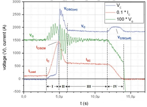
Figure 7 SC 2 fault test waveform[2]
It should be noted that the conditions required by SC 2 are more stringent than those required by SC 1. Although the drive circuit can limit the shutdown voltage Vc/scoff, it cannot limit Vc/scon. Vc/scon may exceed the rated voltage of the device [2]. Because the di/dt of the second stage is uncontrolled.
SC 2 fault waveforms, as shown in Figures 8 and 9:
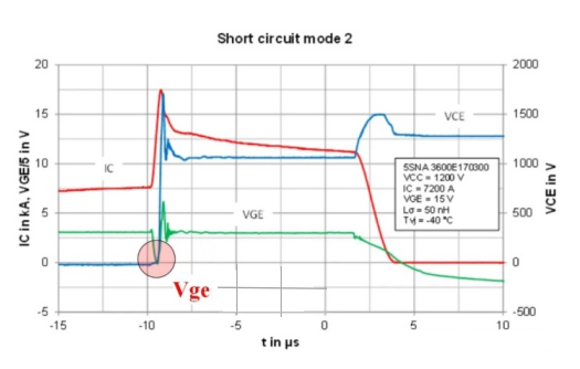
Figure 8 SC 2 fault test waveform[1]
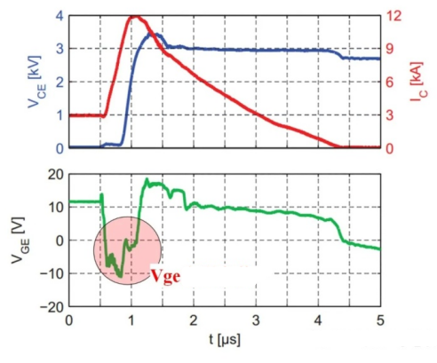
Figure 9 SC 2 fault test waveform[3]
6. Short circuit fault SC 3
The SC 3 fault refers to the short-circuit behavior of the lower IGBT when the IGBT is kept on and the diode is conducting current at the last moment when the short-circuit occurs. SC 3 can be simulated with the circuit shown in Figure 10.
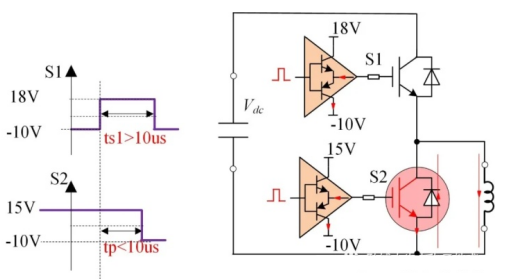
Figure 10 SC 3 short circuit test circuit
The SC 3 short circuit waveform is shown in Figure 11. When a short circuit occurs, the IGBT is forced to turn on, similar to the forward recovery process of a diode, and the IGBT also has a forward recovery, mainly because the conductance modulation of the bipolar power semiconductor device requires certain time. The forward recovery peak voltage mainly depends on the di/dt speed, which can be as high as several hundred volts on the wide-base high-voltage IGBT (the internal stray inductance and di/dt effect of the module also contribute to a certain extent), the waveform behind the forward peak and the SC 2 The analysis is basically the same.
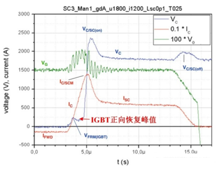
Figure 11 SC 3 fault test waveform[2]
It is conceivable that since the IGBT has a forward voltage, the parallel diode will also have a reverse recovery process, so the ISC in Figure 11 includes both the forward conduction current of the IGBT and the reverse recovery current of the parallel diode.
